CFD Analysis of NREL Phase VI wind turbine
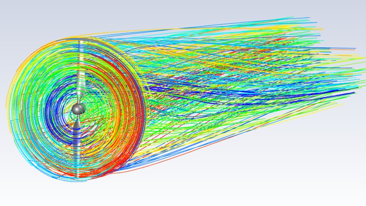
Why take this course?
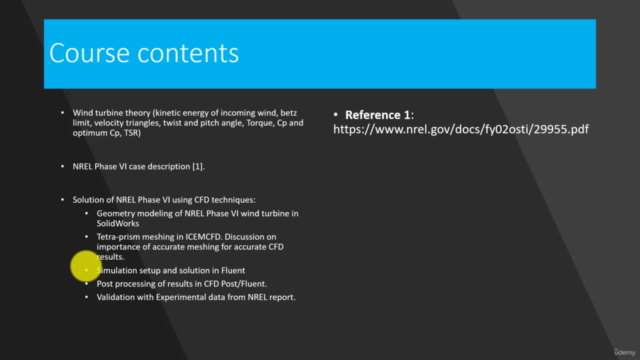
To complete the tasks outlined in the instructions, you'll need to follow a series of steps involving CAD modeling, mesh generation with ICEMCFD, and fluid dynamics simulation with ANSYS Fluent. Here's a detailed guide on how to proceed:
Step 1: CAD Modeling with SolidEdge or Similar
-
Model the Wind Turbine Blade:
- Start by modeling a single blade with the given dimensions and the specified radial coordinate.
- Apply a global pitch angle of 3 degrees to the blade.
-
Create Two Blades Using Pattern Command:
- Use the pattern command in SolidEdge to replicate the initial blade twice, resulting in two blades.
-
Model the Hub:
- Create a sketch for the hub with a higher radius than the end point of the wind turbine blade (0.508 m).
- Use the pull command to extrude the sketch and create the 3D solid body for the hub.
-
Join Blades and Hub:
- Combine the two blades and the hub into a single solid body representing the complete wind turbine model.
Step 2: Domain Creation in ICEMCFD
-
Create Inner Domain:
- Import the solid body representing the inner domain (wind turbine without the support structure) into ICEMCFD.
-
Set Up Mesh Parameters:
- Adjust topology and triangulation settings.
- Run the
build topologycommand to generate initial mesh.
-
Mesh Generation:
- Set sizes on different surfaces as required.
- Define the global mesh size.
- Create a tetra prism mesh for the inner domain using the Octree algorithm and then delete the volume mesh.
- Smooth the surface mesh up to the desired quality.
-
Create Density Box for Mesh Refinement:
- Use density boxes to refine the mesh in the wake region behind the blades.
-
Generate Volume Mesh:
- Create a volume mesh using the Delaunay algorithm.
- Set prism mesh parameters, choose the wind turbine from parts list, and create prism layers (initially 5-7 layers, then split each layer into 3 for a total of 15-21 layers).
-
Redistribute Prism Mesh:
- Use the
redistributecommand to ensure proper mesh ordering.
- Use the
-
Smooth and Check Mesh Quality:
- Smooth the volume mesh with prism elements.
- Ensure high-quality mesh by checking the quality and improving it if necessary.
Step 3: Mesh Generation for Outer Domain in ICEMCFD
-
Import Outer Domain Geometry:
- Import the spaceclaim file representing the outer domain (the region around the wind turbine where flow can occur) into ICEMCFD.
-
Set Up Mesh Parameters:
- Adjust topology and triangulation settings.
- Run the
build topologycommand to generate initial mesh.
-
Mesh Generation for Outer Domain:
- Create a tetrahedral mesh using the Octree algorithm.
- Smooth the surface mesh up to the desired quality.
-
Generate Volume Mesh for Outer Domain:
- Follow similar steps as for the inner domain, ensuring proper mesh distribution and quality.
Step 4: Fluid Dynamics Simulation with ANSYS Fluent
-
Set Up Fluent Case:
- Open ANSYS Fluent and read the saved case file containing both meshes (inner and outer domains).
- Manually create four partitions for parallel processing.
-
Turbulence Model Setup:
- Set the turbulence model suitable for the simulation (e.g., k-epsilon model).
-
Boundary Conditions and Frame Motion:
- Assign the inlet velocity of 7 m/s.
- Set the outer domain as a far field with outflow conditions.
- Apply frame motion to account for the blade rotation at 72 RPM using the
frameMotioncommand.
-
Solver Setup:
- Configure the solver settings with the coupled option as shown in the video.
- Set up autosave for data files every 50 iterations.
-
Torque Monitoring:
- Set up solution monitors for torque, power, and Cp.
-
Initialize Solution and Run Simulation:
- Initialize the solution.
- Run the solver and monitor the convergence.
-
Post-Processing:
- Post-process the results to visualize the performance parameters.
-
Data Analysis and Validation:
- Compare the CFD results for torque, power, and Cp with experimental data from the National Renewable Energy Laboratory (NREL).
-
Documentation:
- Review the accompanying PDF file for explanations on renewable energy and wind turbine dynamics to understand the context of the simulation results.
Follow these steps carefully, and you should be able to successfully complete the CAD modeling, mesh generation, and fluid dynamics simulation of a wind turbine in ANSYS Fluent.
Course Gallery
Loading charts...